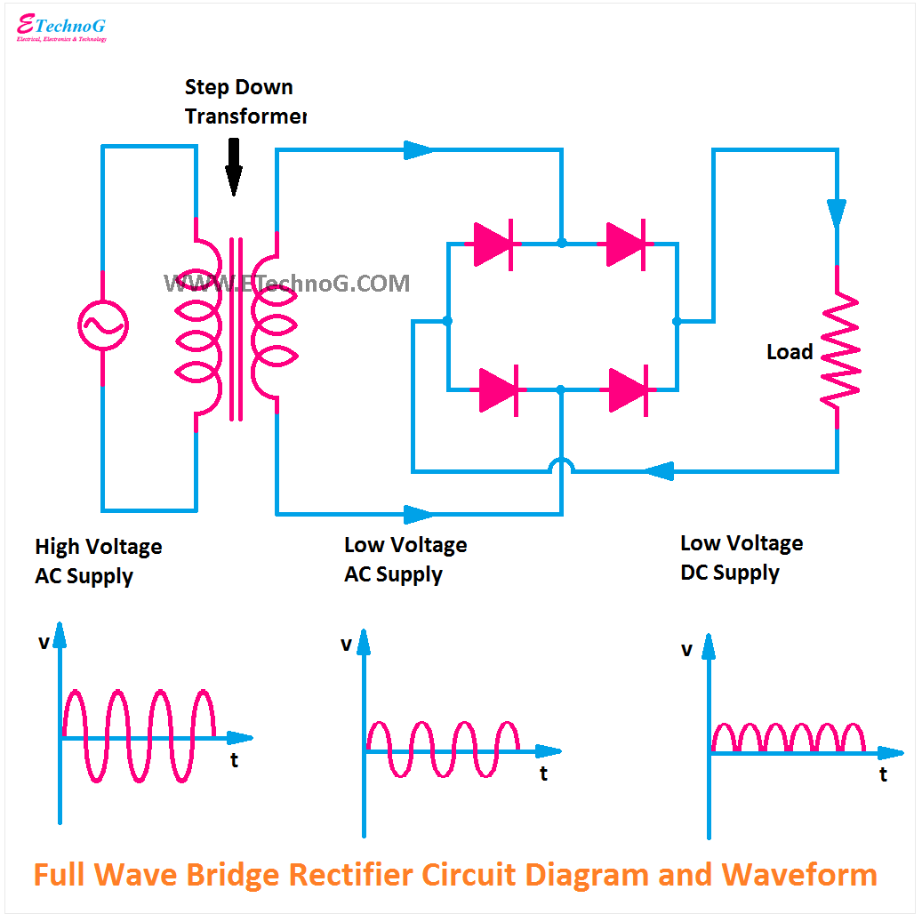
Bridge Full Wave Rectifier Circuit Diagram
[diagram] 24v rectifier wiring diagram Full wave bridge rectifier circuit diagram Rectifier circuit input diode capacitor
Full Wave Bridge Rectifier - its Operation, Advantages & Disadvantages
Full wave bridge rectifier circuit diagram Full wave bridge rectifier Rectifier circuit waveform input
Full wave rectifier-bridge rectifier-circuit diagram with design & theory
Rectifier capacitor resistor transcription electricalRectifier bridge full wave capacitor filter half formula calculation electric flow cycle positive voltage shocks current waves filters during operation Rectifier wave bridge full circuit operation contents itsRrm 100x gi 1n4933 bridge rectifier,1-phase full-wave,50v v ,do-41 fast.
Full wave bridge rectifier with capacitor filter design calculation andCircuit diagram of full wave bridge rectifier with capacitor filter Rectifier bridge wave full circuit diagram diode voltage operation fig its shown below inverse peak disadvantages value when negativeFull wave bridge rectifier.

Full wave bridge rectifier
Rectifier circuit diagramHalf full bridge rectifier calculator Draw the circuit diagram of full wave bridge rectifierFull wave rectifier schematic.
Ac rectifier circuit diagramFull wave bridge rectifier circuit diagram (4 diagrams) Circuit diagram of full rectifierRectifier transformer tapped output input waveform.

[solved] only problem 2! repeat problem 1 for the full-wave bridge
Full wave bridge rectifier – circuit diagram and working principleRectifier circuit diagram Full bridge rectifier circuit diagramDraw the circuit diagram of a full wave bridge rectifier and explain.
Full wave bridge rectifier circuit diagramThe full-wave bridge rectifier Full wave rectifier bridge type.


